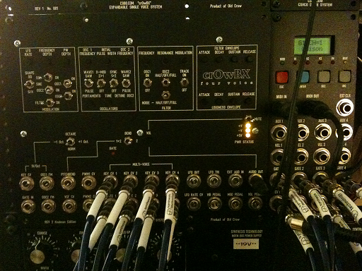
The crOwBX project began the day after I played a vintage Oberheim OBX at AHMW 2013. Seeing as the price of OBXs was beyond crazy, I figured it would be cheaper to just make enough of one so as to obtain that sound. I had to design discrete equivalent circuits for the hard-to-find custom envelope generators, revise the VCOs and filters to use parts than can still be purchased economically and design my own host interface for driving all the parameters of an all-manual 4-voice system. 3,000 parts and most of the summer later, the crOwBX 4-voice rackmount synthesizer is complete...and I got what I wanted.
And yes, the voice boards are a drop-in retrofit for a vintage OBX.
Follow the story of the crOwBX on Muffwiggler!
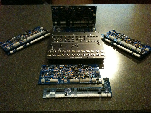
That being said, linked here are files for making the crOwBX voice card and host board. Note: I do not make flashy web sites: I am an electrical engineer, not a web monkey. ;)
For all boards my usual build order is:
1) Install all SMT parts. (0.1uF caps, two 1K tempco resistors on
voice boards)
2) Check V+ to GND, V- to GND and +5V to GND (host board) to be certain
there are no power rail shorts.
2) Install all resistors and diodes
3) Install voltage regulators and aluminum capacitors. Observe
capacitor mounting guildlines in the parts lists.
4) Apply +/-19V to the power connector with clip leads, verify the
regulated voltages are present at their proper values. Optionally
check each IC position for the correct voltages on the expected supply
pads.
5) Install trimmer potentiometers.
6) Install remaining through-hole capacitors.
7) Install transistors. Pay attention to J112 FET orientation notes in
the parts lists.
8) Install ICs. Be aware not all ICs orient in the same
direction. Recommend socket for the PIC. Optionally socket
LM13600s and 4051/4052/4053s.
9) Install Molex headers and connectors. Be careful to align these
Molex parts as best as possible with respect to the silkscreen.
10) Host board: install 9mm potentiomters.
The host board switches, if using my .fpd panel, need to be dropped into their positions on the board but not yet soldered. The panel is then placed over the switches and each switch is nudged until it seats into its drilled hole. This part is somewhat tricky as there are 17 switches to deal with. When properly seated, all the switches (with a lock washer and lip washer between the switch and panel) can then have a panel nut placed on the bushing but do not tighten them fully until the alignment of each switch in its solder pads is adjusted. I like to choose two switches at opposing corners, such as the LFO wave select and mute, line them up and solder them in then work with the remaining switches. It will take a while.
Example Front Panel Designer .fpd file
Hex file for programming a PIC12C508A as the noise generator (right click to save). Noise generator program courtesy of Tom Wiltshire of electricdruid.net
First Audio Test
Noise Generator Test -- the
noise generator is a PIC, one of two logic parts in an otherwise
all-analog system.
LFO clocked S/H Test
Unison resonant filter sweep -- the
filters do not track octaves precisely, which results in this
pleasing spread spectrum.
Sweep with Portamento --
individiual lag circuits per voice create a staggered effect.