Owing to the fact that CS-series machines are all now over 20 years old, certain repairs should be performed to keep the instrument as reliable as possible. As described in my servicing tips article, many of the analog switch and logic chips in the machine are candidates for replacement. Using a friend's CS-80 sent to me for repair as an example, I will outline the repairs I did to restore the following problems:
2) Voice #3 is silent no matter which key is pressed.
3) In Sustain-I mode with long release, note pitches would drift up. Also, some notes would portamento quickly up to the pitch of the stuck voice #1 note.
4) Polyphonic aftertouch inoperative except on C# and G keys.
5) Of the LEFT, GENERAL, RIGHT audio output jacks, only the LEFT jack is working, but as if it were the GENERAL (both synthesizer sections) output. The same is true for the PHONES ouput jack.
1) Looking at the CS-80 schematics, something had to be wrong in the pitch control voltage path from the key assigner to the synth voice boards for voice #1. Measuring voltages on the KAS (key assigner) circuit board indicated the KAS circuit was working properly for voice #1. Moving on to the SH board, a problem showed itself: the output of the 4016 bilateral switch attached to the hold amplifier for voice #1 was stuck at 10 volts! Since the 4016 is operating from +8.5V and -6.5V DC supplies, the 10 volts must be coming from the hold amplifier. Removing the hold amplifier silenced the stuck high note, but the expected control voltage entering the SH board for voice #1 was not appearing on the amp-side of the 4016. The 4016 must have also failed, probably due to age.
I decided to replace all the 4000-series chips on the SH board while waiting for the new CA3140T parts to arrive (T package = round metal can, kind of hard to find anymore). I used machine-pin sockets for the DIP parts; also notice the empty circular location awaiting the new op-amp:
After installing the new CA3140T, voice #1 was fully operational again (although it needed tuning):
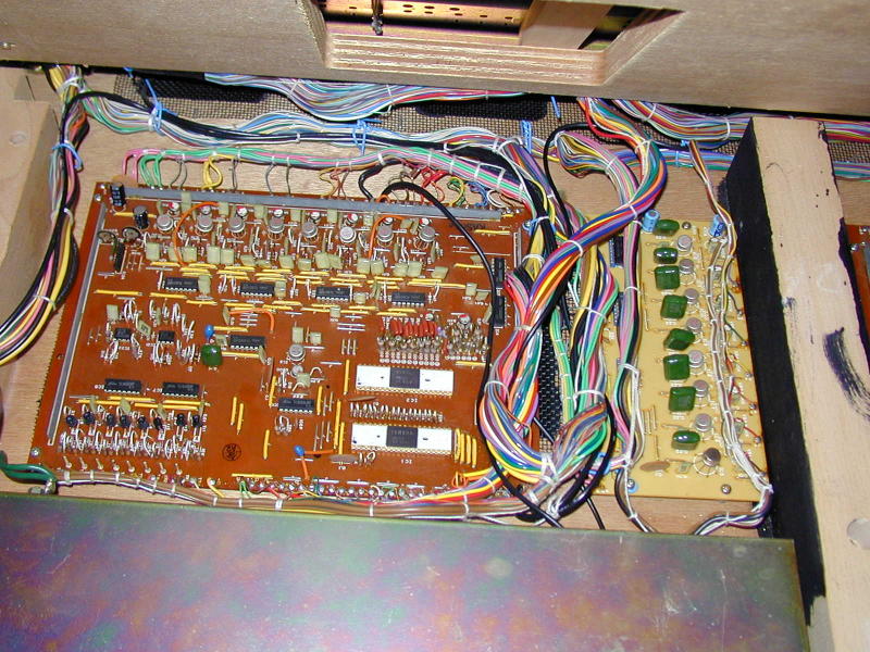
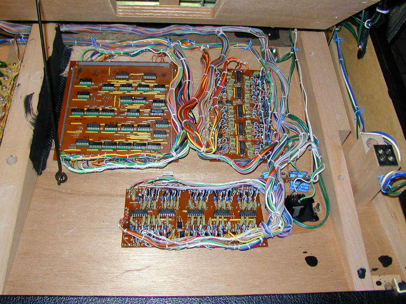
Above, you can see the KAS board (larger board with two 40-pin DIPs on it) and the repaired SH board with the new op-amp and DIP parts.
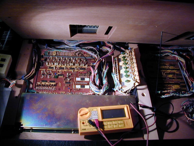
2) Voice #3 being silent, I decided first to check the trigger output for it coming from the KAS board. Triggers are supposed to go from +8.5V (off) to -6.5V (active low) as keys are pressed. This was fine for Voices 1, 2 and 4 through 8, but voice #3's trigger was +7.5V to -2.5V--quite a ways off. I decided to replace the transistor in the trigger level-converter for voice #3. I did not have a 2SA561 transistor, but as a simple switch just about any standard PNP transistor would work. I used a 2N3906. I lifted the KAS board and installed the new transistor:

Hey, check out the prop-rod used to hold up the keyboard. Just like working on your car, heh heh. The only trick to using the 2N3906 was that its leads were EBC order whereas the 2SA561 leads were ECB order. A short piece of wire insulation is the solution here, allowing the B and C leads to cross without shorting. The only problem after swapping transistors was...no change in observed trigger voltages.
Now, understand that I was solving the voice #1 and voice #3 problems simultaneously. I decided that if voice #1's control voltage was stuck and the 4016 feeding it was broken on that channel, it is possible the 4011 attached to that 4016 was also broken. This line of thought is what lead to the replacing of the four 4000-series chips on the SH board, aside from the age problem. After replacing the chips, voice #3 was alive again. OK, so I replaced a transistor that was probably fine, but hey, 3 leads are easier to desolder than 4x14. ;)
3) Wonderful luck! Repairing the SH board for problems 1 and 2 also removed problem 3! Old 4000-series CMOS does strange things when it deteriorates...
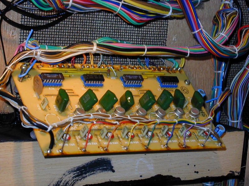
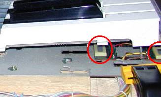
4) With all eight voices alive again, it was time to tackle the polyphonic initial+aftertouch. Under each key is a force-sensing resistor aka FSR (circled in red):
These sensors produce a voltage based on the amount of pressure on the key. Now, since there are 61 sensors but only 8 voices, something must be done to select the appropriate sensors and route them to the proper modulation control circuits for the 8 voices. This is the task of the TKC board. Now, if you read my article on repair tips, you will notice I made mention of the TKC board already. It wins the "Oops!" award for board design in that there are no decoupling capacitors on the board at all! There are 28 chips and not a single bypass capacitor. Nothing to do for it but remove every old chip and install a socket (note where I used a sharpie to write the chip numbers on the board):
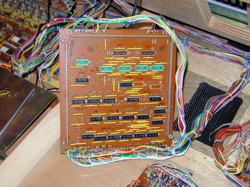
Then, install a bypass/decoupling capacitor for each chip. It would have been nice if the factory had removed the solder flux when the board was orginally built. Melting the old flux, I determined the board-builder was a smoker: the flux traps airborne particles like smoke as it solidifies and releases them again when melted. Time to get out the jug of 1,1,1 trichloroethylene...
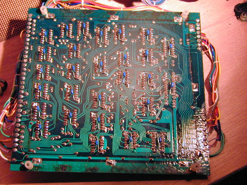
Stuffed new chips into sockets. The TSB1 and TSB2 boards also pictured here got new 4051 chips in sockets:
And the polyphonic pressure system was working again...mostly.