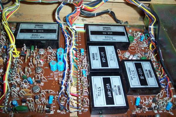
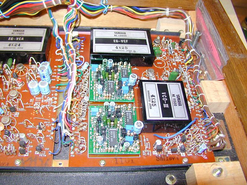
This is the voice card of a Yamaha SY-2, which uses the same resin-potted submodules that a GX-1 uses:
I wanted to see what the feasibility was in crafting new modules as Yamaha wasn't being helpful in obtaining the engineering data (they "lost" it). So, I bought some organic epoxy solvents and a short chem lab experiment later...
OK as insane is this melted module looks, I was able to reverse-engineer the circuit with some careful digging, lots of measuring and a bit of hammer-and-chisel. These pictures show the very end of the process where my destructive analysis totally destroyed the NE10500 HPF VCF submodule. It was not this bad in the beginning, although it still was not exactly pretty. If someone else really wants to try this stunt, my first response is: DON'T! This was very difficult for someone used to ripping things apart. The chemicals are dangerous, and using them will dissolve half the parts even if it does soften the epoxy. Standard disclaimer applies: don't blame me if you break something.
I had some help, of course. I must thank Juergen Haible and Harry Bissell for their help in determining certain aspects of the filters--these guys went so far as to run the circuit models through SPICE and plot curves at varying resonances, etc.
So what is it? It is a very compact diode-ring Sallen-Key filter, with a voltage-controlled impedance cell to adjust resonance. The circuits for the HP and LP filters are nearly the same, which meant these could actually be made as one board with a couple of judiciously-placed jumpers and a few minor part value changes. And so, these were born--very likely the first GX1 filter modules made in nearly 30 years:
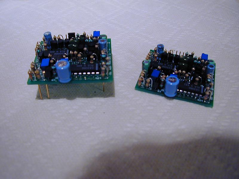
The only three major differences are the original filters used CA3019 diode arrays, 2SA561 PNP and 2SC458 NPN transistors and the filter board was mounted inverted over the main PC board. I used CA3086 B-E junctions for my matched diodes, 2N3906/2N3904 for the transistors and I inverted the layout so that the modules do not have to mount upside-down to the host PC board. Otherwise they are the same. I may change the 2SK30A FET to a 2N3819, but I had some K30As on hand. I will eventually have schematics and sound samples up comparing my SY-1 (new filters) vs. my SY-2 (original filters).
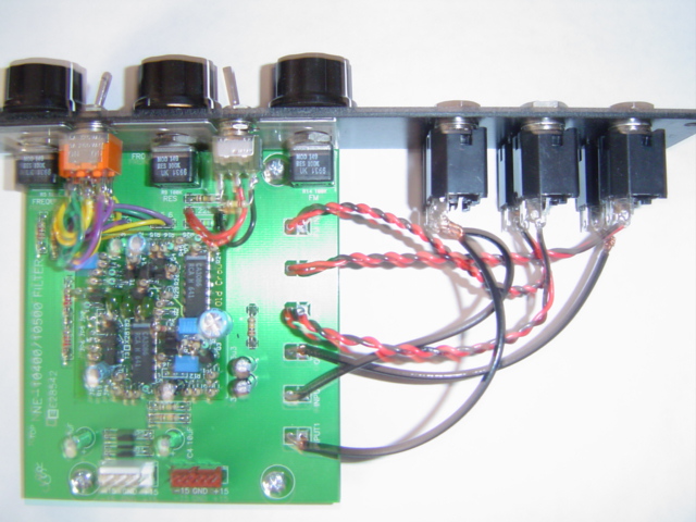
Here they are installed in the SY-1:
If I ever make these in any quantity for GX1 owners, they'll definitely be converted to surface-mount! Cramming 12 transistors, 2 ICs, 45 resistors, 8 capacitors, 3 trimpots and a couple of jumpers and module pins onto a 1.75 x 2 inch board is quite cramped.
Here is a WAV file of the new filters in action. This file is 3.8 megs in size (45 seconds at 16-bit 44.1KHz mono). I didn't want to use any lossy compression formats as they inevitably color the sound.
Operation notes: the V/I converter is exponential; the diode cell response introduces a large amount of intermodulation distortion at high resonance levels, which is what gives the filter a distinct character. As with most Yamaha filter designs, these do not self-oscillate at high Q, although with some tweaking they can be made to squeal rather "grungily." In the SY-1/SY-2/GX-1, the filters are arranged LP feeding HP. Later Yamaha equipment, such as the CS-80, use a HP feeding LP arrangement. It should be noted the GX-1 also has a second HP filter as well as a BP filter in a separate signal path than these "main" filters. The extra filters are not controlled by envelope generators, but are rather used to select specific harmonics from the VCO waveforms to be mixed in to each voice.
Some more pix:
My prototype of the MOTM-485 using a compact NE filter module. Hey Konkuro, notice the power connector I put on there just for you? ;) (Sadly, I learned of my friend Konkuro's (John A. Mitchell) death in the summer of 2004. He was a very skilled modular synthesist and simply put--a great guy. I will call the spare power connector on every module I make from now on KONKURO PWR in his memory).
1U front panel made for me by Stooge Larry. Note switch for HP or LP mode, switch for full or 1/2 tracking (a Yamaha thing on HP filters) and CV jack for resonance.
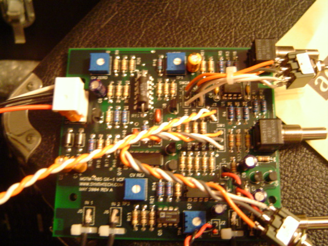
MOTM-485 production prototype of filter PC board. This can't be all-discrete audio path--look at all those chips! Actually, there is only one IC on there, and it is the op-amp that is part of the CV front-end. Everything else is die-matched but otherwise electrically discrete transistor arrays. Four trimpots are visible, but final version will only need two.
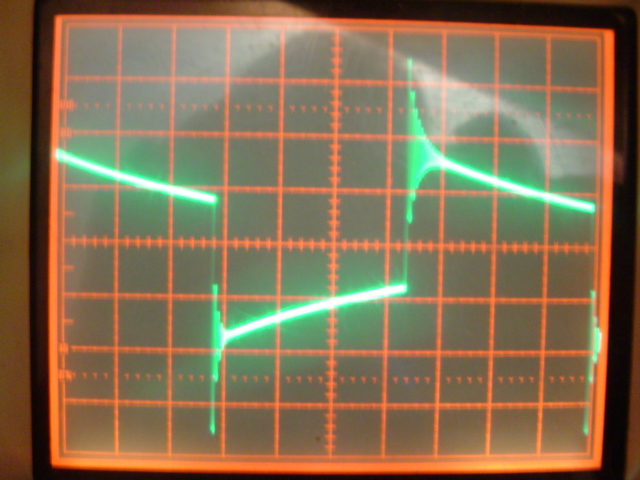
Scoped output of filter in LP mode set wide open, using pulse waveform input and resonance at mid-scale (Q of 5 or so).
Audio examples of the MOTM-485.
More later.