While working on two different CS-80s in the spring of 2001, I took several pictures of the internal layout. First, a quick example of how to raise the circuit board rack to the service position. Click on any image to enlarge.
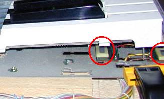
After raising the hood (requires loosening two screws on the underside of the machine--pictures will be added eventually), the circuit board rack and keyboard assembly can be seen. The rack has two screws holding it to the rack frame supports on each side. These screws must be removed first:
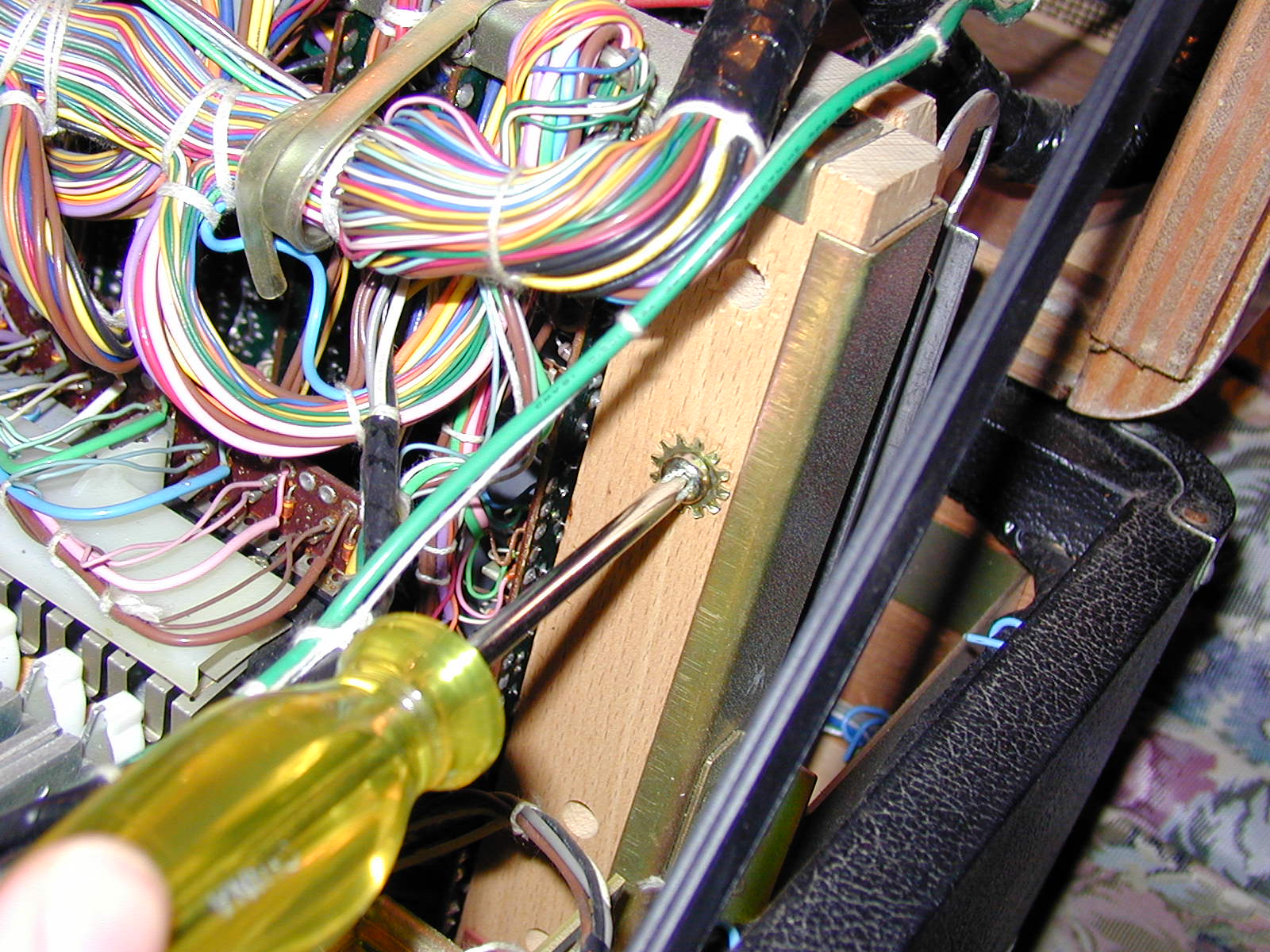
The hole just below the green wire had a screw+lockwasher as well. Once the screws on both side are removed, the wiring bundles secured to the wood staves at each end of the rack need to be freed from the stiff, blue pieces of wire used to hold them to the stave. These blue holding wires can be brittle, and may break due to age--no big deal. In the above image, the bundle of wires on this end can be seen next to the green ground wire. Also: see the broken holding wire pieces laying on the tolex? If a holding wire breaks, just remove it from the case and discard--they were there mainly for keeping the wiring from pulling loose due to road transport. By now I hope any working CS-80 is strictly for studio use.
In any case, once the screws are removed and the wiring bundles loosened from their holders, the rack can be raised to the service/tuning position. It is best if two people do this as the length of the rack makes moving it rather unwieldy. The idea is to grasp the top of the rack frame (near the middle if one person is trying this, otherwise two people grab it near either end) and pull up evenly until the locking clips rotate and seat themselves on the guide rails:
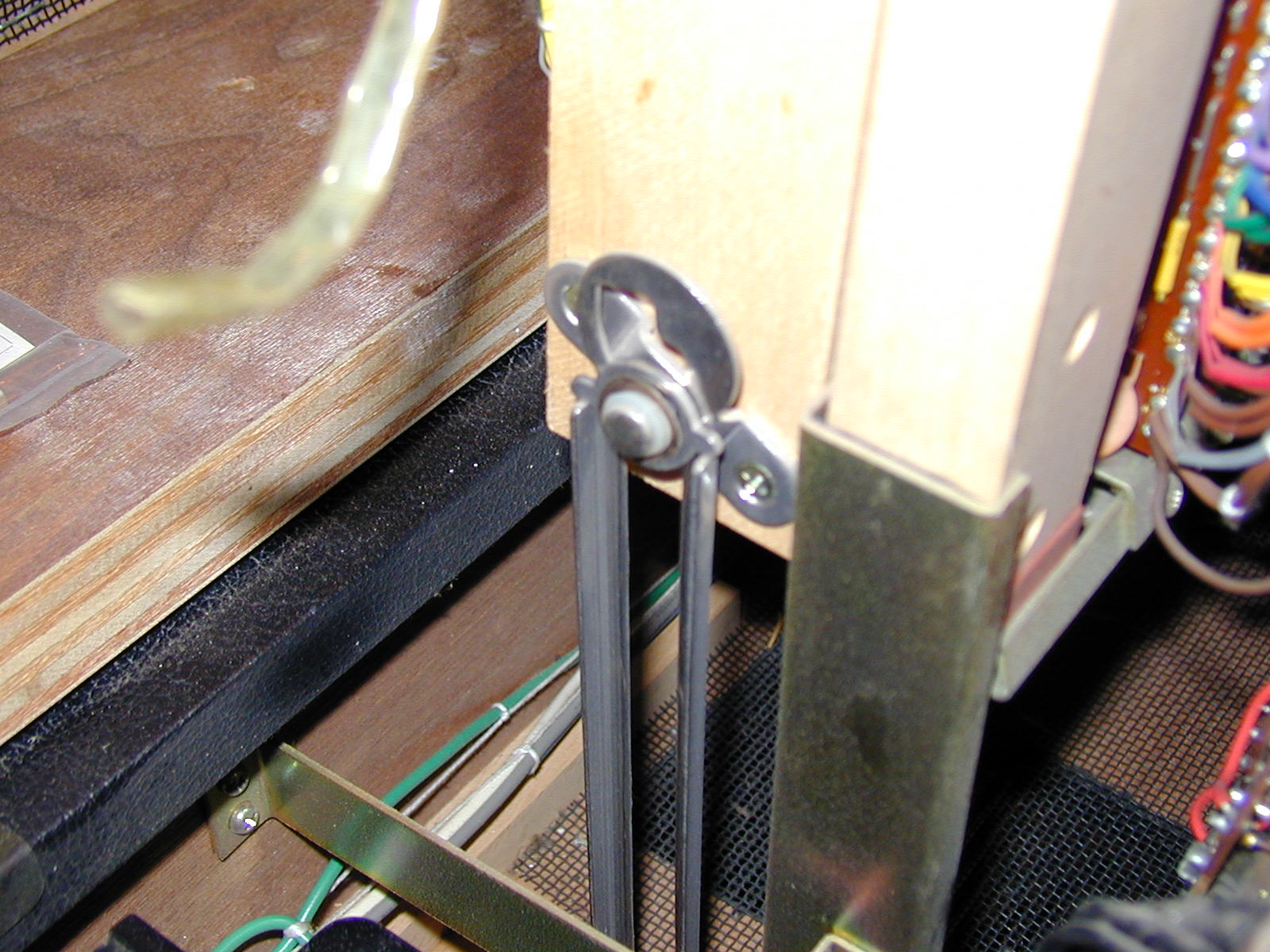

The locking clips are the round washers that have little "wings" on either
side, sort of like this: 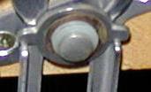 Raising the rack causes
these locking clips to rotate into the position shown. When lowering the
rack, it is actually raised slightly to get the clip to rotate to the
vertical position at which point the rack can slide back down to be
secured in the 'normal' position. That odd litle J-shaped cut-out just
above the clip is what causes the roatation, by the way.
Raising the rack causes
these locking clips to rotate into the position shown. When lowering the
rack, it is actually raised slightly to get the clip to rotate to the
vertical position at which point the rack can slide back down to be
secured in the 'normal' position. That odd litle J-shaped cut-out just
above the clip is what causes the roatation, by the way.
Here is the result after raising the rack:

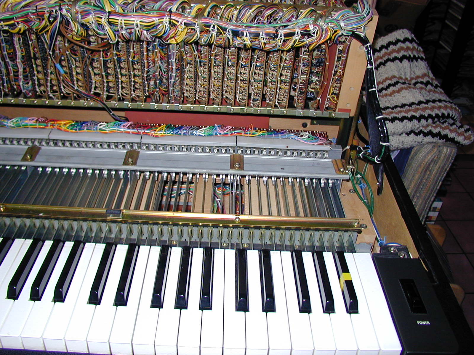
On the left can be seen the rather large power supply, which weighs in
at around 20kg. There are three fuses mounted in a fuse-block on the top
of the supply: one for AC and two for the unregulated DC positive/negative
voltages. In both images, the steel weighted-action keyboard is obvious.
Each key arm has a plastic key cap attached to a 45cm steel 'rib'. On the
far end of the rib is a counterweight and felt-covered switch paddle that
pushes against two switches when played. One switch is the note value,
the other is the initial velocity detection switch. This is repeated for
each key: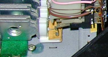
For the polyphonic aftertouch key pressure, a force-sensing resistor is
positioned under a tab that is part of each plastic keycap: